- Spanish-Latin America
- Japanese-JP
- Chinese
- Europe
- Português-BR

Tech Support
(888) 598-9901
Hours: Mon-Fri 8AM-8PM EST
nep-usa@site_ea168614-f5f4-4298-bd5b-880b4cf8d99d
What Is a 12 Port Fiber Termination Box?
A 12 Port Fiber Termination Box is a compact enclosure for organizing and protecting fiber optic connections. It typically supports up to twelve fiber ports, although the exact capacity depends on its internal design. Some models manage pigtails, adapters, splice trays, and incoming cables in one controlled space. Others focus mainly on connector termination. That difference matters.
In real installations, technicians use this box in communication rooms, building networks, surveillance systems, and small data centers. A well-designed enclosure keeps fibers bent safely and prevents loose cables from becoming a maintenance problem. It may include SC, LC, or other adapter types, so compatibility must be checked before purchase. Port labeling also helps technicians trace connections without disturbing active lines. Small details often save time.
The box should provide protection from dust, accidental pulling, and unnecessary fiber movement. Its material, sealing level, mounting method, and cable-entry structure affect long-term reliability. However, a higher port count does not automatically mean better performance. Fiber quality, connector cleanliness, bend-radius control, and installation skill remain equally important. This is where product descriptions can be slightly misleading.
A careful evaluation should consider working environment, fiber type, splice requirements, and future expansion. For example, a wall-mounted box may suit a compact office, while a rack-compatible design may serve a central cabinet better. Inspectors should also verify routing space and grounding needs where applicable. The best choice is not always the largest one. It is the enclosure that keeps connections organized, accessible, and stable over time.
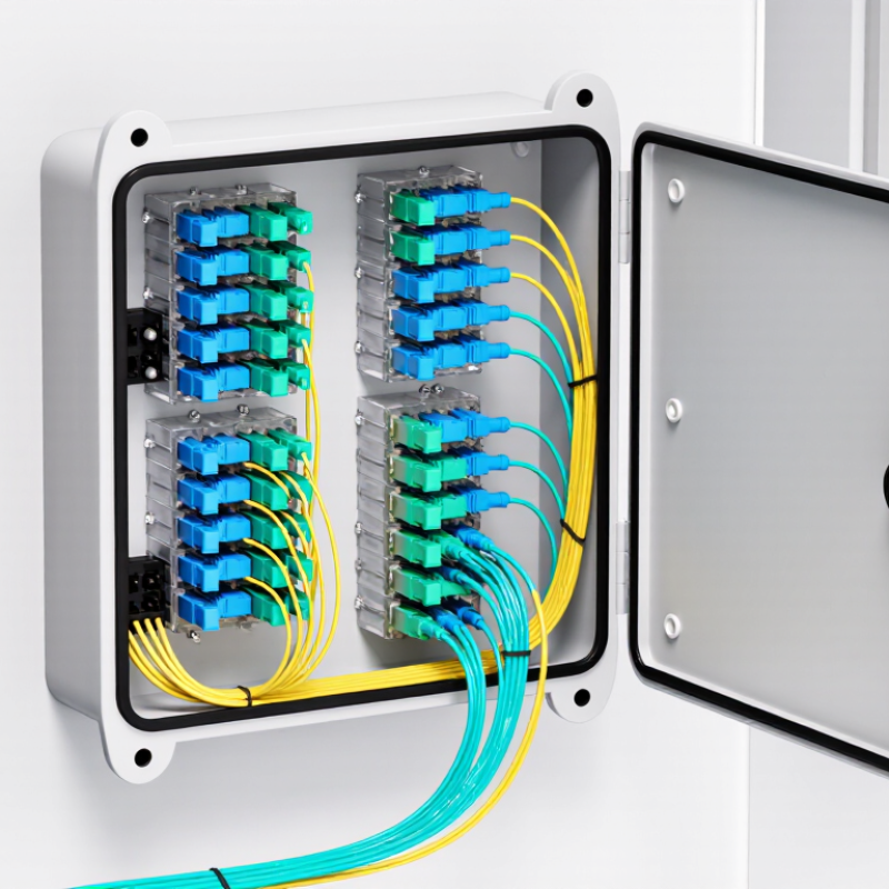
Definition and Purpose of a 12-Port Fiber Termination Box
What Is a 12 Port Fiber Termination Box?
A 12-port fiber termination box is a compact enclosure for organizing and protecting fiber connections. It usually holds twelve adapters, splice trays, or termination points. Technicians use it at building entrances, distribution cabinets, and small network rooms. The box separates incoming cables from outgoing patch cords. This makes testing, maintenance, and fault isolation more manageable.
Its main purpose is protection and orderly fiber management. A sealed enclosure limits dust, moisture, and accidental cable movement. Internal routing also helps control bend radius, which reduces optical loss and long-term damage.
The OECD Broadband Statistics report showed that fiber represented about 42% of fixed broadband connections across OECD economies in December 2023. That growth increases the need for compact termination equipment. A 12-port design suits limited-capacity installations, but capacity planning can be imperfect. Future expansion may require another box or a larger enclosure.
Tips: Check connector type, cable entry size, splice capacity, and IP rating before installation. Leave gentle service loops inside the box. Avoid tight bends and crowded adapters. The ITU-T G.657 recommendation supports bend-insensitive fiber designs, but installation quality still matters. Label every port clearly. Record test results after termination, including insertion loss and return loss. These small records often save hours during troubleshooting.
Get in touch
Our mission is to develop cutting-edge clean energy technology and provide next-generation solar inverters.
Phone
(888) 598-9901
nep-usa@site_ea168614-f5f4-4298-bd5b-880b4cf8d99d
