- Spanish-Latin America
- Japanese-JP
- Chinese
- Europe
- Português-BR

Tech Support
(888) 598-9901
Hours: Mon-Fri 8AM-8PM EST
nep-usa@site_ea168614-f5f4-4298-bd5b-880b4cf8d99d
What Is a Stator Tester and What Types Are There?
A stator can look clean, run quietly, and still hide serious electrical damage. Turn insulation may be aging between windings. A loose connection may create heat inside the slot. These faults often appear before smoke, noise, or a complete motor failure.
A Stator tester helps technicians measure those hidden conditions. It may check winding resistance, insulation resistance, phase balance, or dielectric strength. More advanced systems perform surge tests and compare electrical waveforms. Some testers work offline in a workshop. Others support online monitoring while the motor remains connected to equipment. Each method reveals different evidence. None provides a perfect diagnosis alone.
Ricky Smith, a recognized reliability and maintenance expert, often states, “You cannot maintain what you cannot measure.” That principle fits stator testing closely. A technician must connect the correct leads, control the test voltage, and record results consistently. A small reading difference can matter. So can temperature, cable length, and previous repairs.
The main types include handheld resistance testers, insulation resistance testers, surge testers, hipot testers, and multifunction motor analyzers. Their prices and capabilities vary widely. Choosing the strongest instrument is not always wise. The correct tester depends on motor size, voltage, duty cycle, and maintenance goals.
This guide explains what a Stator tester measures and how each type works. It also examines practical limitations. Test results can be misleading when procedures are rushed. That uncomfortable detail deserves attention. Reliable maintenance depends on careful testing, qualified interpretation, and repeatable records.
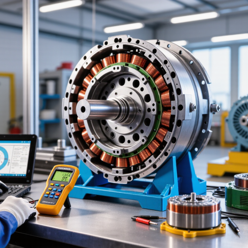
Definition and Purpose of a Stator Tester
A stator tester is a diagnostic instrument for checking the stationary windings inside an alternator or electric motor. Its purpose is simple: identify electrical faults before replacing expensive parts. A reliable test may reveal open windings, short circuits, uneven resistance, or weak insulation. Some testers use a digital multimeter for basic resistance checks. Others apply a controlled test signal and compare winding performance under load.
The correct tester depends on the job. A multimeter suits continuity and resistance testing. A dedicated stator analyzer can measure phase balance, insulation condition, and output behavior more precisely. Technicians often compare each winding against the others, not only against a fixed specification. That matters because a winding can pass a basic continuity test but fail when voltage rises. A single reading can look convincing, yet still be wrong. Temperature, dirty terminals, and damaged connectors can distort results.
Tips: Disconnect power before testing. Let the stator cool. Clean the terminals first. Record every reading. Use the service specification when available, because acceptable values vary by design. Never rely on resistance alone. Check output with the correct test method, and stop if the insulation test exceeds the equipment’s rating. In practice, testers reduce guesswork, but they do not replace careful inspection. Even experienced technicians can misread a result when a connector or ground path causes the real fault.
| Dimension | Stator Tester Type or Feature | Definition, Purpose, and Typical Data |
|---|---|---|
| Basic Definition | Stator Tester | An electrical test instrument used to evaluate the condition of stator windings in AC motors, generators, alternators, and other rotating electrical machines. It helps identify insulation damage, winding faults, phase imbalance, open circuits, short circuits, and connection problems. |
| Primary Purpose | Condition Assessment | The main purpose is to verify winding integrity before installation, during preventive maintenance, after repair, or following a motor failure. Testing can reduce the risk of unexpected downtime and secondary damage caused by electrical faults. |
| Basic Electrical Test | Continuity and Resistance Tester | Measures winding resistance and checks whether each phase has a complete electrical path. The results are compared between phases; a large difference may indicate loose connections, damaged conductors, incorrect winding connections, or localized winding defects. |
| Insulation Test | Insulation Resistance Tester | Applies a controlled DC test voltage between the winding and ground, or between isolated windings, to measure insulation resistance. Low readings can indicate moisture, contamination, aging, cracks, or insulation breakdown. The test voltage must be selected according to the motor and applicable safety procedures. |
| High-Voltage Test | Dielectric Withstand Tester | Applies a voltage higher than the normal operating voltage for a limited time to verify that the insulation system can withstand electrical stress without flashover or breakdown. This is a safety-critical test and should be performed only with suitable equipment, procedures, and trained personnel. |
| Surge Detection | Surge Comparison Tester | Sends short-duration high-voltage pulses through the windings and compares the resulting waveforms. It is primarily used to detect turn-to-turn, coil-to-coil, and phase-to-phase insulation weaknesses that may not be revealed by a simple insulation-resistance test. |
| Inductance Analysis | Inductance or Impedance Tester | Measures electrical parameters such as inductance, impedance, capacitance, phase angle, or dissipation-related values. Differences between phases can help reveal shorted turns, incorrect coil connections, air-gap-related effects, or changes in the magnetic circuit. |
| Core Assessment | Core Loss Tester | Evaluates losses in the stator core after rewinding or mechanical damage. Excessive core loss may result from damaged laminations, shorted laminations, overheating, or improper repair. The test can help determine whether the core remains suitable for service. |
| Magnetic Field Test | Growler-Style Tester | Produces an alternating magnetic field to help locate shorted turns or abnormal magnetic behavior in suitable motor components. It is a relatively simple diagnostic method, although interpretation depends on the motor construction and the operator’s experience. |
| Online Monitoring | Online Motor Condition Monitor | Collects electrical or physical operating data while the motor remains connected to its system. Common indicators include current imbalance, negative-sequence current, voltage imbalance, power factor, load, temperature, and vibration. It supports trend-based maintenance but may not identify every localized winding defect. |
| Offline Testing | De-Energized Diagnostic Tester | Tests the isolated stator while the motor is disconnected from its power source. Offline testing generally provides more direct access to the winding insulation and phase terminals, but it requires lockout, verification of zero energy, proper discharge, and controlled reconnection procedures. |
| Typical Measurements | Electrical Parameters | Common measurements include winding resistance in ohms, insulation resistance in megohms or gigohms, test voltage in volts or kilovolts, leakage current, inductance, impedance, surge waveform response, phase angle, capacitance, and core-loss-related values. |
| Faults Detected | Common Winding Problems | A stator tester may help identify open windings, shorted turns, phase-to-phase faults, phase-to-ground faults, unbalanced resistance, poor terminal connections, insulation contamination, moisture, thermal aging, and damage caused by vibration or overheating. |
| Testing Stage | Manufacturing and Repair | Used to verify newly wound coils, completed stators, repaired motors, and rewound assemblies. Typical checks include resistance balance, insulation resistance, dielectric withstand, surge comparison, and core condition, depending on the machine design and required quality standard. |
| Maintenance Stage | Preventive and Predictive Maintenance | Periodic testing establishes a baseline and allows technicians to compare results over time. A gradual decline in insulation resistance or a growing phase imbalance can indicate deterioration before a complete failure occurs. |
| Result Interpretation | Baseline Comparison | Test results should be compared with manufacturer specifications when available, previous measurements, comparable phases, temperature-corrected values, and applicable technical standards. A single reading should not be interpreted without considering motor size, insulation class, temperature, humidity, and test method. |
| Key Limitation | Diagnostic Scope | No single test detects every stator fault. For reliable diagnosis, technicians often combine resistance, insulation, surge, inductance, core, temperature, vibration, and operating-current information as appropriate for the machine and suspected failure mode. |
| Safety Requirement | Safe Test Practice | The equipment must be isolated, locked out, and verified de-energized before offline testing. High-voltage tests require guarded test areas, appropriate personal protective equipment, controlled discharge after testing, and compliance with site rules and applicable electrical safety requirements. |
Get in touch
Our mission is to develop cutting-edge clean energy technology and provide next-generation solar inverters.
Phone
(888) 598-9901
nep-usa@site_ea168614-f5f4-4298-bd5b-880b4cf8d99d
