- Spanish-Latin America
- Japanese-JP
- Chinese
- Europe
- Português-BR

Tech Support
(888) 598-9901
Hours: Mon-Fri 8AM-8PM EST
nep-usa@site_ea168614-f5f4-4298-bd5b-880b4cf8d99d
How to Choose a Temporary Power Pole for Your Project?
Choosing the right temporary power pole can determine whether a project runs smoothly or faces avoidable delays. Construction sites, outdoor events, agricultural operations, and emergency work often need safe electricity before permanent service is available. A temporary power pole provides that connection, but the correct model depends on more than voltage and outlet count.
The selection process should begin with a realistic load calculation. List every planned tool, light, heater, pump, and charger. Check their starting currents, not only their running watts. A qualified electrician can confirm the service rating, panel configuration, grounding method, and required protection devices. Local electrical requirements also matter. Pole height, weather resistance, cable routing, GFCI protection, and utility approval may vary by location.
Think about the site itself. A muddy building lot may require stronger anchoring than a compact event area. Exposed wires, standing water, vehicle movement, and changing weather can create practical hazards. Choose equipment with suitable ratings, clear labeling, durable enclosures, and documented testing from a recognized authority. Reliable suppliers should provide installation guidance, inspection records, and responsive technical support.
Small details matter.
In practice, teams sometimes estimate demand too quickly and regret it when new equipment arrives. I have seen a site plan change after installation, leaving outlets in inconvenient positions and extension cords across walkways. That experience suggests allowing reasonable capacity, access, and future adjustment. A careful comparison of temporary power pole options can protect workers, equipment, schedules, and budgets without treating safety as an afterthought.
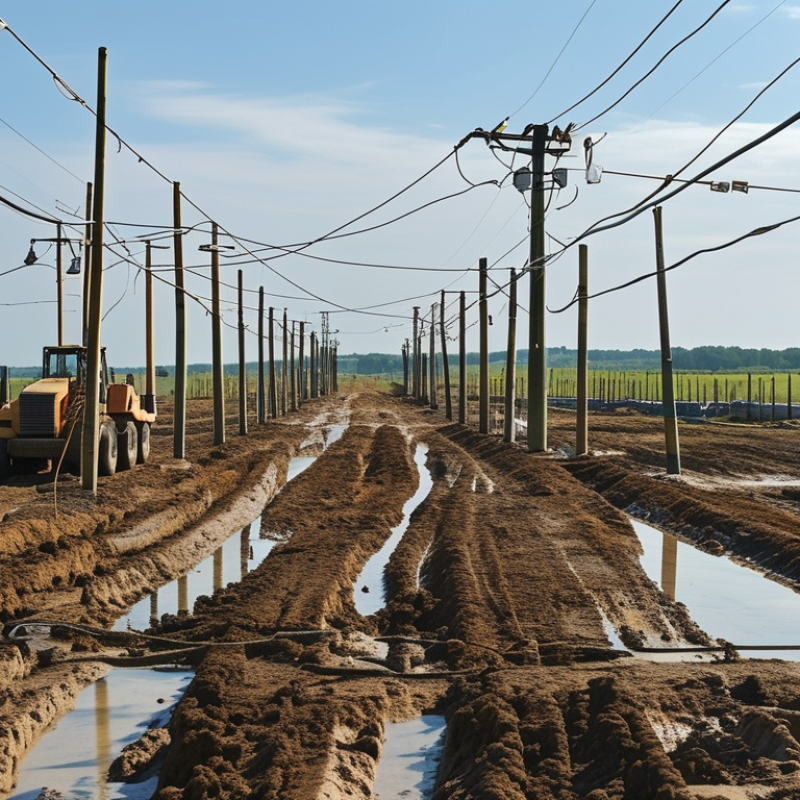
Define Project Demand: 120/240 V, 60 Hz Loads and 100–200 A Service
Choosing a temporary power pole begins with the project’s actual electrical demand, not the pole’s appearance. For many construction sites, the target is 120/240 V at 60 Hz with service between 100 and 200 A. This split-phase supply supports ordinary 120 V tools and larger 240 V equipment. List every load, including saws, compressors, heaters, pumps, lighting, and office equipment. Record both running watts and starting current. Motors can briefly demand several times their normal current.
A 200 A service does not mean 200 A is always available for continuous use. Apply the appropriate load calculation, then allow capacity for future tools and unexpected demand. Check the pole’s panel rating, breaker arrangement, grounding method, enclosure protection, and cable size. Long feeders may create voltage drop, especially when a compressor starts in cold weather. I have seen neat temporary installations perform poorly because cable distance was ignored. That mistake is easy to repeat.
Select a pole with a stable base, clear circuit labeling, weather-resistant components, and enough outlets for safe cord routing. Keep the pole away from vehicle paths, standing water, and material storage. A qualified electrician should verify the service configuration, grounding, overcurrent protection, and local inspection requirements before energizing it. Do not rely on a rough estimate or a familiar setup. Project conditions change, and the safest choice may be a larger service than the first calculation suggests.
Related Posts
-

2026 Top Trends in Temporary Power Pole Usage and Innovations?
-

2026 Top Electricity Saving Box What You Need to Know?
-

China Top 10 Energy Rates Trends You Should Know About?
-

Best Solar Powered Outlet Solutions for Global Buyers?
-

10 Essential Tips for Using an Electricity Saving Box Effectively?
-
Why Choose a Solar Powered Attic Fan for Your Home?
Get in touch
Our mission is to develop cutting-edge clean energy technology and provide next-generation solar inverters.
Phone
(888) 598-9901
nep-usa@site_ea168614-f5f4-4298-bd5b-880b4cf8d99d
