- Spanish-Latin America
- Japanese-JP
- Chinese
- Europe
- Português-BR

Tech Support
(888) 598-9901
Hours: Mon-Fri 8AM-8PM EST
nep-usa@site_ea168614-f5f4-4298-bd5b-880b4cf8d99d
How to Choose Hot Swappable Switches for Keyboards
Choosing Hot Swappable Switches can transform a keyboard’s sound, feel, and daily comfort. However, the right choice depends on more than attractive packaging or popular reviews. A quiet linear switch may feel smooth during office work, while a tactile switch can provide a noticeable bump for faster typing feedback. Clicky switches create a sharper sound, but shared spaces may make them impractical. Small details matter. Spring weight, actuation distance, housing quality, and stem design all influence the experience beneath your fingertips.
Before buying, check your keyboard’s socket compatibility and switch pin configuration. Most hot-swap boards support common three-pin or five-pin MX-style switches, but exceptions exist. Manufacturer specifications should guide your decision. Independent testing and long-term user reports can reveal problems that product pages omit, such as inconsistent springs or premature chatter. I have chosen switches by sound alone before. That was a mistake. A pleasant recording did not always match the tiring feel of a full workday.
This guide explains how to compare Hot Swappable Switches with practical criteria. You will learn how to match switch types with typing habits, gaming needs, noise limits, and budget. Simple tests can help. Try a small sample pack before purchasing a large set. Notice whether your fingers bottom out, whether the return feels controlled, and whether the sound changes across keys. Personal preference remains important, but informed preference is more reliable. There is no perfect switch. Only a better match for your hands, keyboard, and environment.
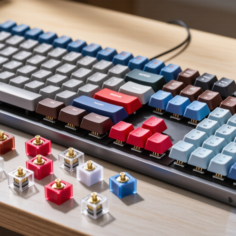
Switch Compatibility: Compare 3-Pin and 5-Pin Hot-Swap Standards
When choosing hot-swappable switches, check the socket standard before chasing sound or force curves. A three-pin switch uses two metal contacts and one central plastic guide. A five-pin switch adds two plastic stabilizing legs. Therefore, a five-hole PCB accepts both designs, while a three-hole PCB usually needs three-pin switches or careful leg trimming.
This distinction matters on a desk, not only on a specification sheet. Five-pin switches feel steadier during off-center presses, especially on wide keys. However, the plate also affects stability. A tight metal plate can support a three-pin switch surprisingly well. It can also make some five-pin housings feel cramped. Measure the PCB and plate together.
A 2024 mechanical-keyboard market outlook projects roughly 8% annual growth through 2030, reflecting wider interest in modular boards. Yet industry compatibility reports rarely publish switch-failure rates by pin count. That gap deserves caution. Do not treat five pins as automatically better.
Test one switch first.
Insert it gently. Never force bent contacts into the socket. A multimeter can confirm electrical continuity, while a small key tester reveals wobble and return problems. Hot-swap sockets are commonly rated for hundreds of replacement cycles, but real results depend on alignment and handling. My own fitting checks have shown that a loose plate can exaggerate housing movement, making a good switch seem defective. That is an easy mistake.
How to Choose Hot Swappable Switches for Keyboards - Switch Compatibility: Compare 3-Pin and 5-Pin Hot-Swap Standards
| Comparison Dimension | 3-Pin Hot-Swappable Switch | 5-Pin Hot-Swappable Switch | Compatibility Guidance |
|---|---|---|---|
| Standard pin layout | Two metal electrical pins plus one central plastic guide post. | Two metal electrical pins, one central plastic guide post, and two additional plastic alignment legs. | Confirm that the switch uses the common MX-style layout before checking the number of pins. |
| PCB hole requirement | Requires holes for the two metal pins and the center guide post. | Requires the same three holes as a 3-pin switch plus two holes for the extra alignment legs. | A PCB designed for 5-pin switches normally accepts both 5-pin and 3-pin versions, provided the socket layout matches. |
| Use on a 3-pin PCB | Directly compatible when the electrical pins and center post align with the PCB. | Usually not directly compatible because the two extra plastic legs may interfere with a solid PCB surface. | The two extra plastic legs can often be carefully clipped flush, converting the switch to a 3-pin form. Check the switch construction first. |
| Use on a 5-pin PCB | Usually electrically compatible, but the unused alignment holes leave less mechanical support. | Directly compatible when the switch socket spacing and electrical pin layout match. | A 3-pin switch can be stabilized by a compatible plate, but it may feel less secure during installation without one. |
| Mechanical stability | Adequate with a rigid switch plate; may have more lateral movement on a bare PCB. | Generally provides better alignment and resistance to rotation, especially in plate-free builds. | Choose 5-pin switches for plateless or flexible builds where additional support is useful. |
| Hot-swap socket contact | The two metal pins must enter the socket openings cleanly and vertically. | Uses the same two electrical contacts as a 3-pin switch; the extra legs are mechanical only. | Pin count alone does not guarantee compatibility. Socket type, pin spacing, and switch format must also match. |
| Installation difficulty | Generally simpler because there are fewer alignment points. | Simple on a compatible 5-pin PCB, but extra legs may need removal for use with a 3-pin PCB. | Never force a switch into place; inspect bent pins and alignment holes before pressing it down. |
| Modification required | Normally none for a compatible PCB. | May require trimming the two outer plastic legs for a PCB without the corresponding holes. | Trim only the plastic legs, not the metal electrical pins or center guide post. A modified switch may be harder to resell or reuse. |
| Plate compatibility | Works with plates designed for the selected switch housing and keyboard layout. | Works with compatible plates; the plate must not obstruct the switch housing or interfere with the PCB. | Plate cutout dimensions can vary, so verify the plate specification separately from the 3-pin or 5-pin designation. |
| Best use case | Keyboards with a fixed plate, 3-pin PCB, or builds where simple installation is preferred. | Keyboards with a 5-pin PCB, plateless designs, or builds that prioritize stronger switch alignment. | For the widest unmodified compatibility, a 5-pin PCB generally offers more mounting options than a 3-pin PCB. |
| Important limitations | The 3-pin label does not confirm compatibility with every hot-swap keyboard; low-profile, optical, magnetic, and non-MX formats may use different dimensions or contacts. | The 5-pin label does not confirm compatibility with every PCB; switch travel, housing height, socket design, and electrical technology still need to match. | Before purchase, compare the keyboard PCB specification, switch format, socket arrangement, plate design, and operating technology. |
Get in touch
Our mission is to develop cutting-edge clean energy technology and provide next-generation solar inverters.
Phone
(888) 598-9901
nep-usa@site_ea168614-f5f4-4298-bd5b-880b4cf8d99d
